nord brake motor wiring diagram
See MG 1-221 MG 1-224 Direction Of Rotation. For specific Leeson Motor Connections go to their website and input the Leeson catalog in the review box you will find connection data dimensions name plate data etc.
2
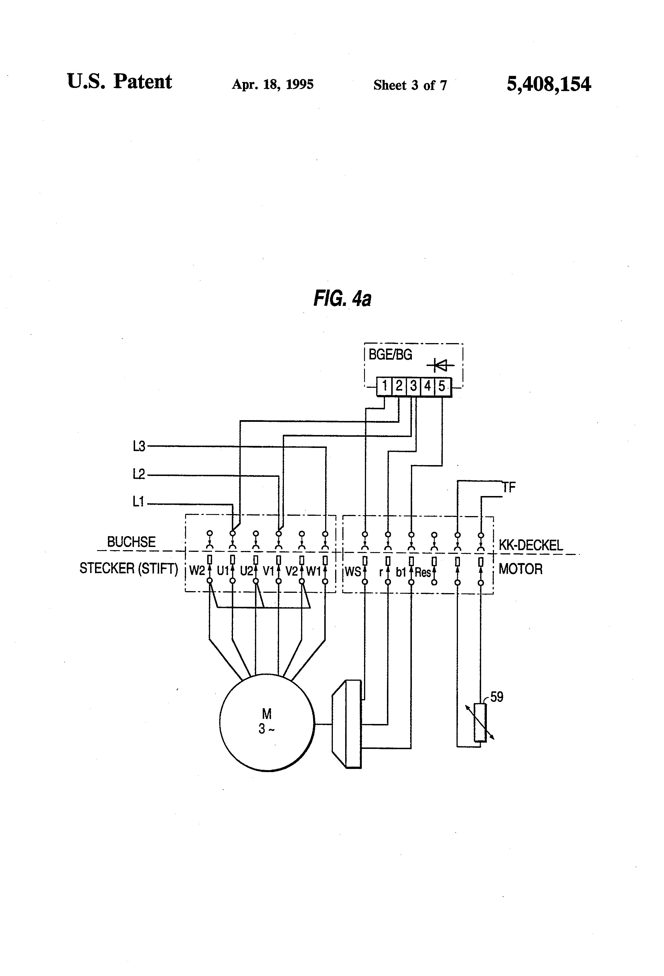
Signal leads from resolver and thermal motor protection THTF on terminal strip Fig.
. Hammond Power QC05DTCB Buck-Boost Transformer 50kVA 1 3Ph 240 X 480 Pri24 X 48 Sec Nema 3R Enclosure Copper Windings. If the air gap exceeds the maximum allowed for that brake configuration provided in the manual adjust the air gap. 323 Motors with plug connector The diagrams show the connector pin assignment for the cable on the connecting side rear.
It is important that the coupling is properly positioned. An electromechanical brake is controlled and released with this DC voltage. Make absolutely sure that no voltage is applied while work is being done on the gearbox.
NORD Gear Corporation - Midwest 800 NORD Drive PO Box 367 Waunakee WI 53597 Phone. Gallery Of Bauer Gear Motor Wiring Diagram Download. Terms and Conditions NORD Gear Corp - Midwest 800 NORD Drive PO Box 367 53597 WI Waunakee Phone.
A three-phase motor must be wired based on the diagram on the faceplate. Motor Start and Stop pushbuttons are wired to the Brake Control Board. Motor power supply lines are located on the board Fig.
2-11 in which vector 1 is 120 degrees in advance of vector 2 and the phase sequence is 1 2 3. Motor Brake On motors that have a brake use a feeler gauge to check the air gap in between the brake pad and the rotor according to NORD Gear Corporation Manual BIM-1090 Motor Brakes Installation and Maintenance Instructions. Pre-stop Mode initiates the brake cycle when the Start push button is pressed.
The terminal box lower section as well as the IS lower section are referred to as adapter plate in the parts lists. Collection of bauer gear motor wiring diagram. 8883146673 NORD Gear Limited Toll Free in Canada.
Finally a word about brake motors. Connect the brake supply cable inserted into the motor terminal box according to the diagram on the inside of the box cover while connecting the brake with the motor maintain all the necessary safety measures and precautions pertaining to the handling of electrical equipment 9. Variety of nord motor wiring diagram.
Switchable pole motors NORD UNIVERSAL motor Standard motors Single-phase motors Smooth motors Synchronous Motors NEW. Connect motor according to wiring diagram. Its got a 230v 3 phase motor so Im planning on installing a VFD and run it off my single phase power supply - as I have already done with my drill press.
It shows the components of the circuit as streamlined shapes and also the power and signal links between the devices. Service 1 Brake Coil 점검. 100 Frame Motor with 4 poles Brake 100 Nm with a hand.
You find information on how to wire the upper part of the IS plug connector in the AC MotorsAC Brake Motors operating instructions. Always use wiring diagram supplied on motor nameplate. Only across-the-line or full-voltage motor control should be used with these motors.
Three Phase--see below Single Voltage. Brake Motor Wiring Diagram Best Nord Exceptional Sew Eurodrive On this website we recommend many images about Sew Eurodrive Wiring Diagram that we have collected from various sites from many image inspiration and of course what we recommend is the most. The detailed operating instructions and wiring diagrams.
Nord motor wiring diagram Whats Wiring Diagram. Applicable AC motors Integral motors and brake motors - M series ME series IEC-normalized motors and brake motors - BN series BE series Single and dual speed motors Main brake features DC and AC supply Faster brake engagedisengage through electronically Controlled ACDC rectifier type SB NBR SBR options Main motor options. I thought the wiring would be similar to that used previously on my drill press however this saws motor has.
NEMA IEC Motor Adapters NORD Gear supplies a coupling that is to be mounted onto the motor shaft. All applicable national local and system-specific and regulations codes and practices. This user manual applies to NORD Motor products and it pro - vides general information for motor operation installation.
How to Wire a Three Phase Motor. The power supply to the brake is interrupted by switching off the mains voltage. One version has contains a brake internally connected to motor leads.
A wiring diagram is a simplified traditional photographic representation of an electric circuit. Mounting the motor casing onto the brake and fan completes. TERMINAL MARKINGS AND INTERNAL WIRING DIAGRAMS SINGLE PHASE AND POLYPHASE MOTORS MEETING NEMA STANDARDS See Fig.
Many motor manufacturers offer two types of brake motors. 8006684378 Brake Control Rectifiers NORD brake control rectifiers convert AC voltage to DC volt-age. A wiring diagram is a streamlined conventional photographic representation of an electrical circuit.
Hammond Power C1F003lES Encapsulated Dry Type Distribution Transformer 3kVA 1Ph 240 X 480 Pri120240 Sec Nema 3R Enclosure Aluminum Windings. It shows the elements of the circuit as streamlined forms and also the power and signal links between the gadgets. Tools required Standard tools Torx 20 screwdriver Wire strippers Hexagon key.
The magnetic field of the brake reduces and the brake is applied after a delay. Symbols that represent the ingredients inside the circuit and lines that represent the connections between. LOCK OUT POWER before any maintenance is performed.
Wiring diagrams are made up of certain things. That being said there is a wide range of different motors and what you have on hand. Electric Motor Wire Marking Connections.
The Brake cycle includes opening of a motor starter contactor sensing the safe voltage level closing the brake contactor injecting DC current into motor winding brake action then. The first step is to figure out the voltage of your phases. As such on cannot use separate power sources for brakes and motors.
In the United States for low voltage motors below 600v you can expect either 230v or 460v. The brake rectifier converts the mains voltage into a DC voltage. A wiring diagram is a schematic which uses abstract pictorial symbols showing each of the interconnections of components in the system.

Transmission Cradle Homemade Tools Floor Jack Homemade

Dc Break Magnetic Wiring Diagram Hoist Break Connection 190v Dc Break 3phase Motor Dc Break Youtube

Single Phase Motor Forward And Reverse Wiring Youtube
The Basics Of Built In Motor Protection For Beginners

Diagram Of All Car Parts En 2021 Voiture Electrique Smart Fortwo Voiture

Wiring Diagram For 220 Volt Single Phase Motor Http Bookingritzcarlton Info Wiring Diagram For 2 Electrical Diagram Electrical Wiring Diagram Electric Motor
2

Unique Wiring Diagram Century Ac Motor Diagram Diagramtemplate Diagramsample Diagram Wire Diagram Chart

Ac Voltage Switching Versus Dc Voltage Switching Of A Rectifier Avsld International

Engine Brake Diagram Chart Air Brake Brake System Freightliner

T100 Triumph Motorcycle Wiring Diagrams Triumph T100 Triumph Power Wire
2
2

Peterbilt Engine Brake Wiring Diagram
2

Pin By Alicia Ramirez On Npr Truck Repair Repair Manuals Crankshaft Position Sensor

Le Stockage De L Energie Branchement Panneau Solaire Eolienne Panneau Solaire
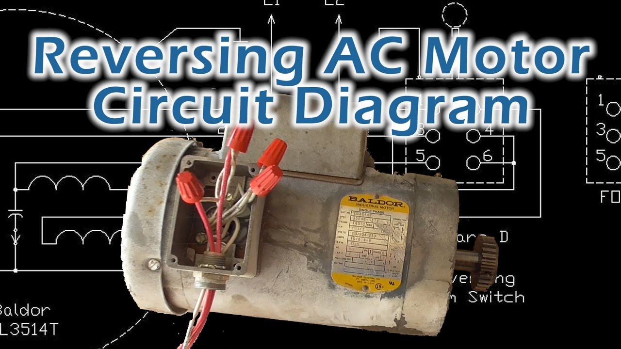
Reverse Baldor Single Phase Ac Motor Circuit Diagram Youtube
Stearns Brake Wiring Diagram Wanyaziz92